Cisco Compatible SFP Modules
Cisco Compatible SFP Modules provide a flexible and reliable solution for expanding your network’s capabilities. These modules are designed to support seamless connectivity across various networking environments, making them ideal for businesses and IT professionals seeking dependable performance. With Cisco Compatible SFP Modules, you can easily upgrade or enhance your existing infrastructure to meet growing data demands. Explore a wide selection of options to find the right fit for your network requirements.
Sort






Why transceiver compatibility goes beyond a matching port
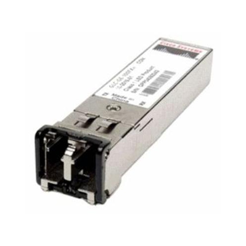
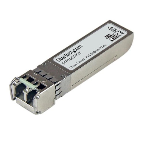
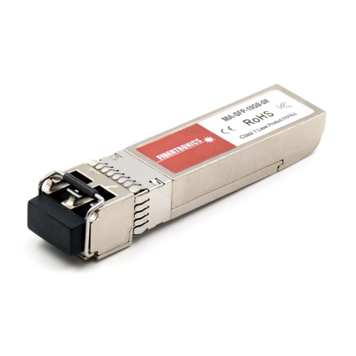
Compatible SFP modules connect network equipment to fibre optic or copper cabling through a compact, removable transceiver. SFP stands for small form-factor pluggable, a format commonly found on managed switches, routers, network interface cards, and other networking equipment. Rather than tying every port to one cable type or transmission distance, a pluggable module allows a supported port to use the connection suited to its role. That might mean a short fibre link between two racks, an uplink connecting office floors, or a longer connection between buildings. These modules are practical components for IT teams, network installers, small-business owners, and experienced home-lab users expanding or maintaining a network. Compatibility involves more than whether the module slides into the port. The host platform, port type, supported data rate, software version, and transceiver coding all help determine whether a module will be recognized and operate correctly. A module described as compatible with one equipment family is not automatically suitable for every switch or router from that manufacturer. Platform-specific compatibility information and the host equipment’s transceiver documentation provide a firmer basis for selection than physical appearance alone. Third-party modules may contain identification data programmed for particular host platforms, but that coding does not replace verification of the exact hardware and software combination. Manufacturer support policies can also differ from technical compatibility, so both matter in networks with formal service requirements. For a business connecting workstations to a central server room, the right module is part of a complete link: the ports at both ends, the cable between them, and any intervening patch panels must work together. Within the broader category of Optical SFP Transceiver Modules, differences in speed, wavelength, connector layout, and supported reach help distinguish modules intended for nearby equipment from those designed for longer fibre runs.
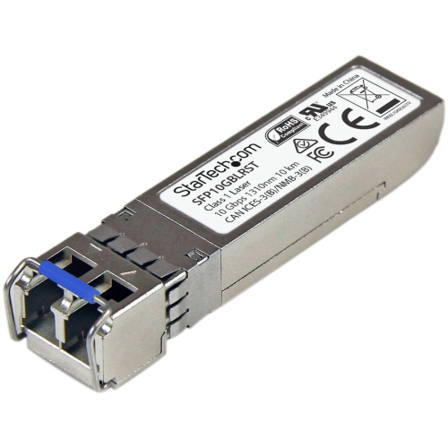
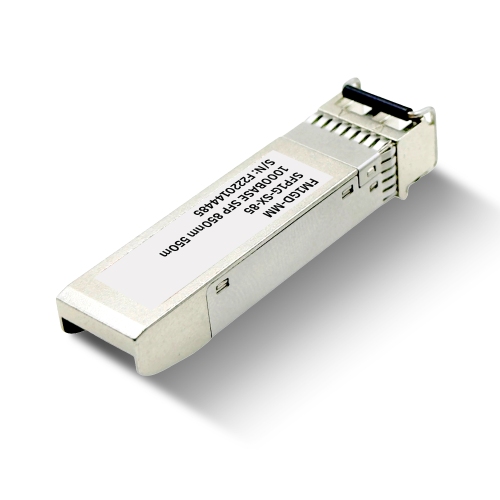
Speed and cable matching are central considerations when comparing compatible transceivers. Standard SFP modules commonly support 1 Gigabit Ethernet, while SFP+ modules commonly support 10 Gigabit Ethernet. Although their housings look similar, a standard SFP port does not become a 10 Gigabit port simply because an SFP+ module fits inside it. Some SFP+ ports also support 1 Gigabit modules, but this depends on the host equipment rather than the form factor alone. Optical modules also need to match the installed fibre. Multimode fibre is commonly used for shorter connections within buildings, while single-mode fibre supports many longer-distance applications. For example, 10GBASE-SR optics typically use an 850 nm wavelength over multimode fibre, with standard reach figures of up to 300 metres on OM3 cable or 400 metres on OM4 cable. By comparison, 10GBASE-LR optics typically use 1310 nm over single-mode fibre for links up to 10 kilometres. These figures describe common standards, not a guarantee for every installation; cable quality, connectors, splices, and optical loss affect the usable link. A cable route that passes through several patch panels needs consideration beyond its measured length. Connector type matters as well. Many optical SFP and SFP+ modules use LC connectors, often in a duplex arrangement with separate transmit and receive fibres. Bidirectional modules can carry both directions over a single fibre, but they require complementary transmit and receive wavelengths at opposite ends. Two modules with identical bidirectional wavelength assignments are not necessarily a working pair. For conventional duplex links, the transmit side at one end must connect to the receive side at the other. Copper transceivers provide another option where supported, allowing an appropriate host port to connect to twisted-pair Ethernet cabling through an RJ45 socket. Their supported cable category, reach, power requirements, and host restrictions differ from optical modules, making them a distinct choice rather than a direct substitute in every port. A mixed network may use both connection types, with fibre for uplinks and copper where existing cabling and endpoint connections make it appropriate.
The physical construction of an SFP module suits equipment racks and repeated service access, but the optical connections still require careful handling. A typical module combines a compact metal housing, internal electronics, electrical contacts, and a release mechanism that secures it in the host port. Optical versions also contain the components that transmit and receive light through the fibre. The housing protects the assembly during normal use, while the connector openings and contact surfaces remain vulnerable to dust, contamination, and rough handling. In a busy communications cabinet, a strained patch lead or a cable bent sharply against the rack door can affect an otherwise suitable connection. Cable routing, connector clearance, and accessible release tabs therefore matter alongside the module’s specifications. Protective caps help keep disconnected optical interfaces clean, and fibre-specific inspection and cleaning tools are more appropriate than household cleaning materials. Optical connectors should never be viewed directly, since active fibre equipment may emit invisible light. Many transceivers support hot-swapping in compatible equipment, allowing replacement without shutting down the entire device, although the affected link is interrupted and the host manufacturer’s procedures still apply. Electrostatic discharge precautions and careful use of the latch help protect the module and port during installation or removal. For ongoing maintenance, some modules provide digital diagnostic monitoring, also called DOM or DDM, which can report readings such as transmit power, receive power, and supply voltage when the host supports those features. These readings can help a network team distinguish a weak optical signal from a configuration or cabling issue, but they do not replace proper link testing. Longer-reach optics also require attention to both minimum and maximum receive levels: a very short link can need attenuation if the selected module’s optical specifications call for it. In offices, workshops, schools, and home labs, a well-matched transceiver supports the connection the network actually needs without relying on excess reach or an unsupported speed. Clear compatibility documentation, suitable cabling, sensible handling, and accessible diagnostic information are useful qualities for anyone responsible for keeping those links dependable.
Speed and cable matching are central considerations when comparing compatible transceivers. Standard SFP modules commonly support 1 Gigabit Ethernet, while SFP+ modules commonly support 10 Gigabit Ethernet. Although their housings look similar, a standard SFP port does not become a 10 Gigabit port simply because an SFP+ module fits inside it. Some SFP+ ports also support 1 Gigabit modules, but this depends on the host equipment rather than the form factor alone. Optical modules also need to match the installed fibre. Multimode fibre is commonly used for shorter connections within buildings, while single-mode fibre supports many longer-distance applications. For example, 10GBASE-SR optics typically use an 850 nm wavelength over multimode fibre, with standard reach figures of up to 300 metres on OM3 cable or 400 metres on OM4 cable. By comparison, 10GBASE-LR optics typically use 1310 nm over single-mode fibre for links up to 10 kilometres. These figures describe common standards, not a guarantee for every installation; cable quality, connectors, splices, and optical loss affect the usable link. A cable route that passes through several patch panels needs consideration beyond its measured length. Connector type matters as well. Many optical SFP and SFP+ modules use LC connectors, often in a duplex arrangement with separate transmit and receive fibres. Bidirectional modules can carry both directions over a single fibre, but they require complementary transmit and receive wavelengths at opposite ends. Two modules with identical bidirectional wavelength assignments are not necessarily a working pair. For conventional duplex links, the transmit side at one end must connect to the receive side at the other. Copper transceivers provide another option where supported, allowing an appropriate host port to connect to twisted-pair Ethernet cabling through an RJ45 socket. Their supported cable category, reach, power requirements, and host restrictions differ from optical modules, making them a distinct choice rather than a direct substitute in every port. A mixed network may use both connection types, with fibre for uplinks and copper where existing cabling and endpoint connections make it appropriate.
The physical construction of an SFP module suits equipment racks and repeated service access, but the optical connections still require careful handling. A typical module combines a compact metal housing, internal electronics, electrical contacts, and a release mechanism that secures it in the host port. Optical versions also contain the components that transmit and receive light through the fibre. The housing protects the assembly during normal use, while the connector openings and contact surfaces remain vulnerable to dust, contamination, and rough handling. In a busy communications cabinet, a strained patch lead or a cable bent sharply against the rack door can affect an otherwise suitable connection. Cable routing, connector clearance, and accessible release tabs therefore matter alongside the module’s specifications. Protective caps help keep disconnected optical interfaces clean, and fibre-specific inspection and cleaning tools are more appropriate than household cleaning materials. Optical connectors should never be viewed directly, since active fibre equipment may emit invisible light. Many transceivers support hot-swapping in compatible equipment, allowing replacement without shutting down the entire device, although the affected link is interrupted and the host manufacturer’s procedures still apply. Electrostatic discharge precautions and careful use of the latch help protect the module and port during installation or removal. For ongoing maintenance, some modules provide digital diagnostic monitoring, also called DOM or DDM, which can report readings such as transmit power, receive power, and supply voltage when the host supports those features. These readings can help a network team distinguish a weak optical signal from a configuration or cabling issue, but they do not replace proper link testing. Longer-reach optics also require attention to both minimum and maximum receive levels: a very short link can need attenuation if the selected module’s optical specifications call for it. In offices, workshops, schools, and home labs, a well-matched transceiver supports the connection the network actually needs without relying on excess reach or an unsupported speed. Clear compatibility documentation, suitable cabling, sensible handling, and accessible diagnostic information are useful qualities for anyone responsible for keeping those links dependable.
Top selling and popular products
-
 Your price for this item is $165
-
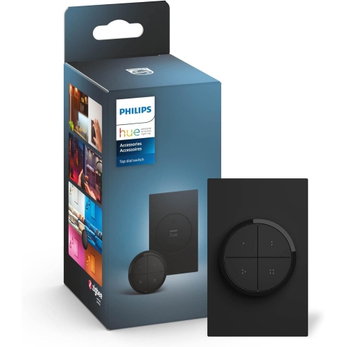 Your price for this item is $96.68
-
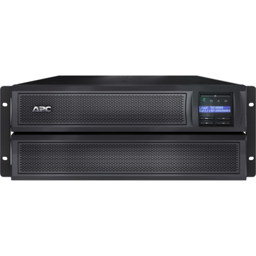 Your price for this item is $3952.99
-
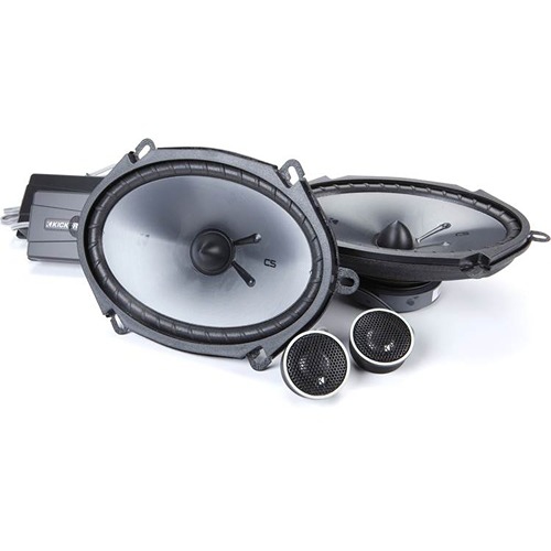 Your price for this item is $229.95
-
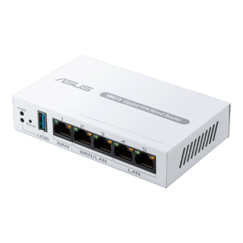 Your price for this item is $119.99
-
 Your price for this item is $280.99
-
 Your price for this item is $234.99
-
 Your price for this item is $173.99
Discover more categories related to Cisco Compatible SFP Modules

Top Collections:
Pokemon Centers, Kindle Devices, Best Cameras for Sports Photography, Pokémon 30th Celebration Cards, Apple iPhones 16, Canon G7X Cameras, iPhone 15 Apple, Flip Phones, Samsung Galaxy Phones, Alarm Clock
Some products may be subject to Environmental Handling Fees
(EHF) depending on your province.
Learn more about EHFs.