Mode Conditioning Patch Cables
Mode Conditioning Patch Cables are essential for optimizing network performance in a variety of professional and home environments. Designed to support reliable data transmission, these cables help ensure seamless connectivity for your fiber optic systems. Whether you're upgrading your current setup or building a new network, Mode Conditioning Patch Cables provide a dependable solution for maintaining signal integrity and minimizing potential disruptions. Explore a wide selection to find the ideal fit for your networking needs.
Sort








Why offset launches matter for existing multimode fibre
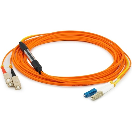
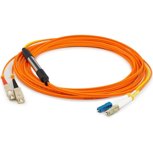
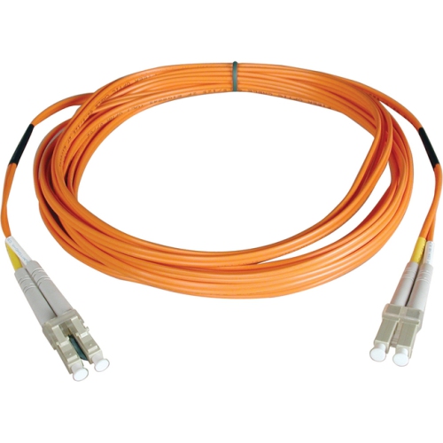
Mode conditioning patch cables are specialized duplex fibre optic jumpers that help compatible laser-based Ethernet transceivers work with existing multimode fibre cabling. Their defining feature is an offset connection between single-mode and multimode fibre on the transmit leg. Instead of launching a narrow beam directly into the centre of the multimode core, this construction introduces the light slightly off-centre, creating a more suitable launch condition for the link. This helps reduce the effects of differential mode delay, or DMD, in which light travelling along different paths arrives at different times and spreads the transmitted pulse. Excessive pulse spreading can make it harder for the receiver to distinguish data reliably, contributing to errors or an unstable connection. Mode conditioning cables are commonly associated with 1000BASE-LX connections over legacy multimode fibre, where the equipment specifications call for this type of launch. For 10GBASE-LRM applications, the need for an external mode conditioning cable depends on the transceiver and the installed fibre, rather than on the connection speed alone. The cable is not an optical signal converter, and it does not turn a multimode cable plant into single-mode infrastructure. Its role is narrower and more practical: providing the appropriate optical launch for a supported combination of equipment and installed cabling. That can be useful in an office building with fibre already routed between communications rooms, a school connecting network cabinets, or a facility retaining established backbone cabling while updating compatible networking equipment. The benefit is compatibility with an existing physical link, not an automatic increase in its rated speed or distance. Supported reach still depends on the Ethernet standard, transceiver specifications, fibre characteristics, and total loss through connectors and splices. A mode conditioning assembly therefore belongs in a deliberately matched optical connection, rather than serving as a general replacement for every fibre patch lead.
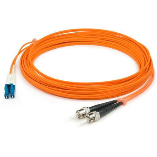
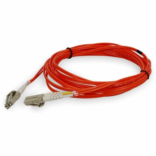
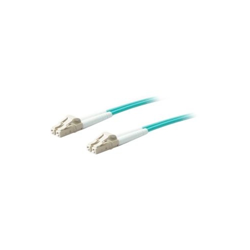
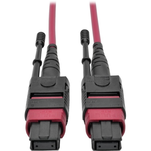
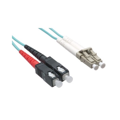
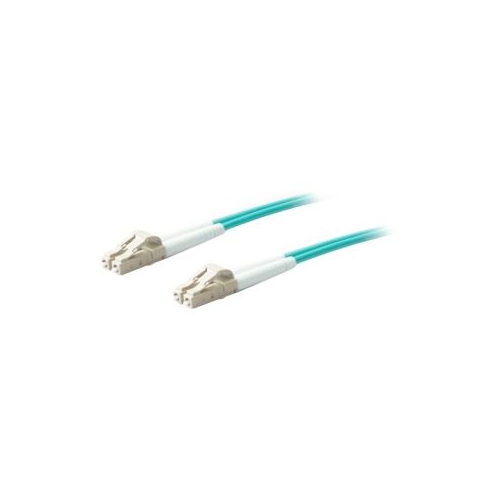
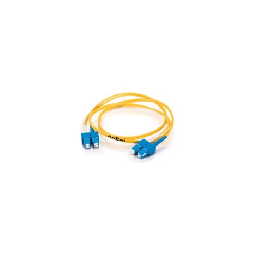
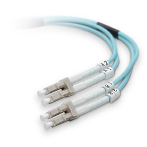
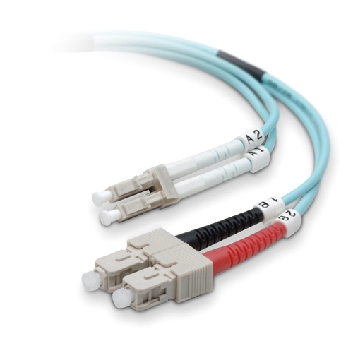
Like other Duplex Fiber Optic Patch Cables, mode conditioning assemblies provide separate paths for transmitting and receiving data, but their specialized construction makes compatibility and orientation especially important. Connector styles such as LC, SC, and ST describe the physical interface, not whether the cable provides the correct launch condition. LC connectors suit compact equipment ports, SC connectors use a push-pull format, and ST connectors have a bayonet-style coupling; the ends must match the equipment and patch-panel interfaces involved. The multimode fibre specification matters just as much. Common core and cladding dimensions include 50/125 µm and 62.5/125 µm, and an assembly intended for one core size should not be assumed suitable for the other. Fibre grade, operating wavelength, connector polish, and the transceiver manufacturer’s requirements also influence the match. Cable jacket colours can provide a useful visual cue, but printed markings and assembly documentation are more dependable than colour alone. On the conditioned transmit path, the single-mode end connects towards the equipment’s transmit port, while the multimode side connects towards the installed multimode cabling. The single-mode section is often identified with yellow marking or jacketing, although identification varies between assemblies. The receive path must also maintain the correct polarity through the complete connection. Where mode conditioning is required for both directions of a duplex link, a matched assembly is normally used at each end, allowing each transmitter to launch correctly into the multimode run. This is why a pair of suitable cables may be needed even though only one continuous backbone connects the two locations. In a cabinet with closely spaced ports and several similar-looking jumpers, clear transmit and receive identification helps prevent a reversed connection or an ordinary duplex lead being mistaken for a conditioned assembly. Length selection also affects fit: enough slack supports orderly routing, while unnecessary loops can crowd a panel and make neighbouring connections harder to trace.
Construction and handling have a direct effect on how well a mode conditioning patch cable stands up to everyday network maintenance. These assemblies combine glass optical fibres, protective coatings and buffers, connector bodies, and an outer jacket; connector ferrules are commonly ceramic to support precise fibre alignment. The offset splice is normally protected within the assembly and is not a user-adjustable feature. Its protection, along with strain relief at the connectors, helps shield the delicate internal structure from routine handling, but the cable still needs routing that respects its specified bend radius and pulling limits. A lead trapped beneath a cabinet door, bent sharply behind a switch, or left hanging under tension can develop excess optical loss even when the jacket looks intact. Patch-management rings and suitable supports help keep the run clear of hinges, fan openings, and frequently accessed equipment. Jacket material and fire rating should suit the installation location and applicable building requirements; a short equipment patch lead should not automatically be treated as suitable for a riser or other building pathway. Cleanliness is equally important because dust or residue on a fibre end face can interfere with light transmission. Protective caps help keep disconnected ends covered, while appropriate fibre inspection and cleaning tools support careful maintenance before connections are made. Wiping a connector on clothing or touching the exposed end face can introduce contamination rather than remove it. Disconnected fibres should never be viewed directly, since optical signals may be invisible. For network technicians, IT teams, and facilities staff, a well-matched assembly is a functional part of maintaining dependable communications between compatible switches and other optical network interfaces. In a busy communications room, the most useful features are often straightforward: legible identification, connectors that fit the intended ports, sufficient reach without excess bulk, and routing that leaves each connection accessible. Keeping the cable specification documented alongside the transceiver and fibre details also makes later servicing less uncertain, particularly when equipment is replaced or a link is moved to another port. The result is a connection selected for its optical requirements and maintained with the same care as the rest of the fibre network.
Like other Duplex Fiber Optic Patch Cables, mode conditioning assemblies provide separate paths for transmitting and receiving data, but their specialized construction makes compatibility and orientation especially important. Connector styles such as LC, SC, and ST describe the physical interface, not whether the cable provides the correct launch condition. LC connectors suit compact equipment ports, SC connectors use a push-pull format, and ST connectors have a bayonet-style coupling; the ends must match the equipment and patch-panel interfaces involved. The multimode fibre specification matters just as much. Common core and cladding dimensions include 50/125 µm and 62.5/125 µm, and an assembly intended for one core size should not be assumed suitable for the other. Fibre grade, operating wavelength, connector polish, and the transceiver manufacturer’s requirements also influence the match. Cable jacket colours can provide a useful visual cue, but printed markings and assembly documentation are more dependable than colour alone. On the conditioned transmit path, the single-mode end connects towards the equipment’s transmit port, while the multimode side connects towards the installed multimode cabling. The single-mode section is often identified with yellow marking or jacketing, although identification varies between assemblies. The receive path must also maintain the correct polarity through the complete connection. Where mode conditioning is required for both directions of a duplex link, a matched assembly is normally used at each end, allowing each transmitter to launch correctly into the multimode run. This is why a pair of suitable cables may be needed even though only one continuous backbone connects the two locations. In a cabinet with closely spaced ports and several similar-looking jumpers, clear transmit and receive identification helps prevent a reversed connection or an ordinary duplex lead being mistaken for a conditioned assembly. Length selection also affects fit: enough slack supports orderly routing, while unnecessary loops can crowd a panel and make neighbouring connections harder to trace.
Construction and handling have a direct effect on how well a mode conditioning patch cable stands up to everyday network maintenance. These assemblies combine glass optical fibres, protective coatings and buffers, connector bodies, and an outer jacket; connector ferrules are commonly ceramic to support precise fibre alignment. The offset splice is normally protected within the assembly and is not a user-adjustable feature. Its protection, along with strain relief at the connectors, helps shield the delicate internal structure from routine handling, but the cable still needs routing that respects its specified bend radius and pulling limits. A lead trapped beneath a cabinet door, bent sharply behind a switch, or left hanging under tension can develop excess optical loss even when the jacket looks intact. Patch-management rings and suitable supports help keep the run clear of hinges, fan openings, and frequently accessed equipment. Jacket material and fire rating should suit the installation location and applicable building requirements; a short equipment patch lead should not automatically be treated as suitable for a riser or other building pathway. Cleanliness is equally important because dust or residue on a fibre end face can interfere with light transmission. Protective caps help keep disconnected ends covered, while appropriate fibre inspection and cleaning tools support careful maintenance before connections are made. Wiping a connector on clothing or touching the exposed end face can introduce contamination rather than remove it. Disconnected fibres should never be viewed directly, since optical signals may be invisible. For network technicians, IT teams, and facilities staff, a well-matched assembly is a functional part of maintaining dependable communications between compatible switches and other optical network interfaces. In a busy communications room, the most useful features are often straightforward: legible identification, connectors that fit the intended ports, sufficient reach without excess bulk, and routing that leaves each connection accessible. Keeping the cable specification documented alongside the transceiver and fibre details also makes later servicing less uncertain, particularly when equipment is replaced or a link is moved to another port. The result is a connection selected for its optical requirements and maintained with the same care as the rest of the fibre network.
Top selling and popular products
-
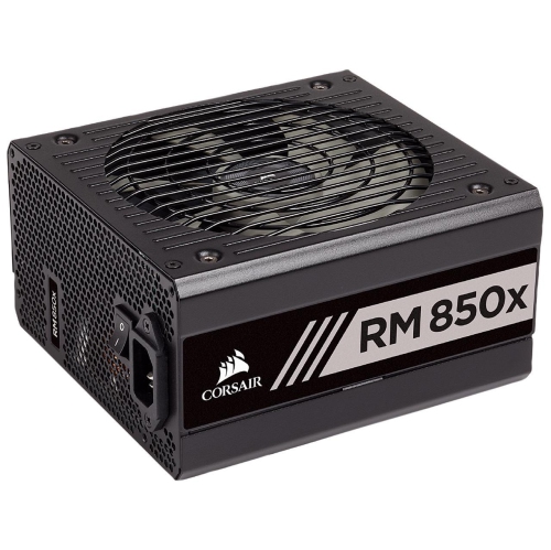 Your price for this item is $199.99
-
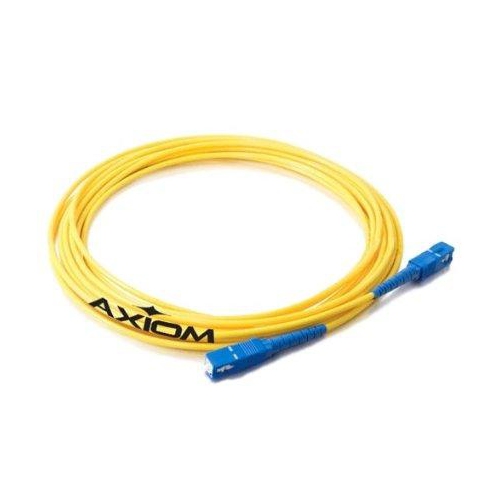 Your price for this item is $45.37
-
 Your price for this item is $46
-
 Your price for this item is $28.99
-
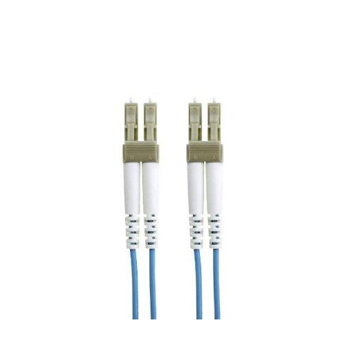 Your price for this item is $77.68
-
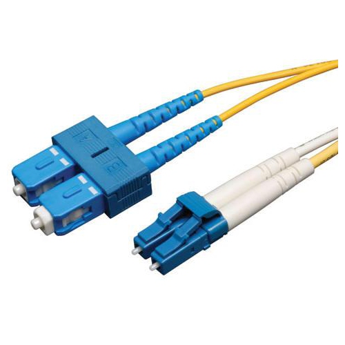 Your price for this item is $36.37
-
 Your price for this item is $57.99
-
 Your price for this item is $11.97
Discover more categories related to Mode Conditioning Patch Cables

Top Collections:
Pokemon Centers, Kindle Devices, Best Cameras for Sports Photography, Pokémon 30th Celebration Cards, Apple iPhones 16, Canon G7X Cameras, iPhone 15 Apple, Flip Phones, Samsung Galaxy Phones, Alarm Clock
Some products may be subject to Environmental Handling Fees
(EHF) depending on your province.
Learn more about EHFs.